
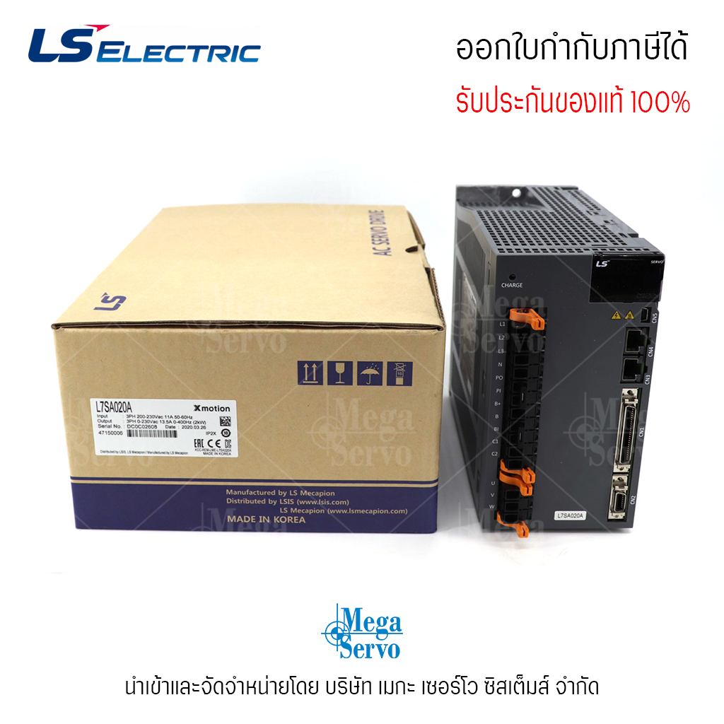
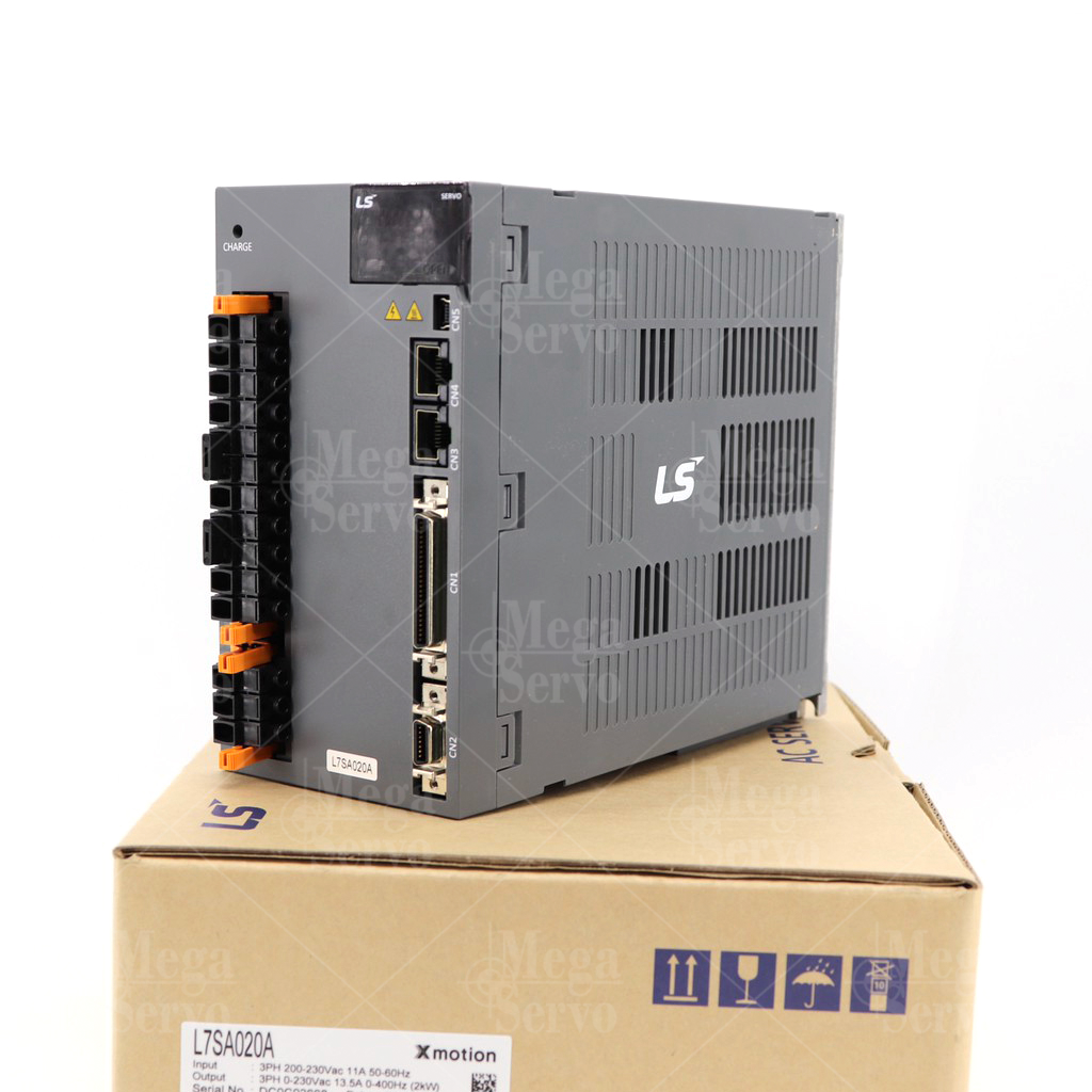
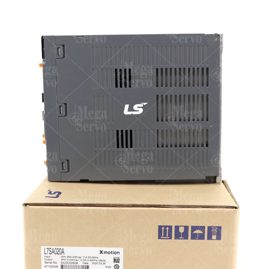
สินค้าใหม่ **มีสินค้าพร้อมส่ง** AC Servo Drive Model:L7SA020A, 2.0kW LS Electric Xmotion
5 ปีที่ผ่านมา
สนใจสินค้า ติดต่อ คุณสมปอง
โทรศัพท์ 092-248-0506


Easy to USE
- Easy Gain Tuning with Automatic Inertia Estimating Function
- Easy Setting Built-in Panel Operator
- Many I/O Contacts and Various Functions
- (Digital Input: 10 contacts, Digital Output:8 contacts / Analog input, output : 2 contacts) ]
Reliability for Protection Function
- CE, RoHS Certificated
- Drive Protection Function and Warn Function
High Response for Precision Control
- High Resolutions Serial type Encoder (19Bit, BiSS)
- Improved Speed Response (≒1Khz) Frequency

 บริษัท เมกะ เซอร์โว ซิสเต็มส์ จำกัด
สมัครสมาชิกร้านนี้ เพื่อรับสิทธิพิเศษ

▲
▼
รายการสั่งซื้อของฉัน
รายการสั่งซื้อของฉัน
ข้อมูลร้านค้านี้

บริษัท เมกะ เซอร์โว ซิสเต็มส์ จำกัด
บริษัทเป็นตัวแทนนำเข้า "LNC" CNC Controller และจำหน่าย AC Servo Motor , AC Servo Drive , Rotary Encoder “ LS MECAPION นำเข้าจากประเทศเกาหลี พร้อมทั้งบริการและติดตั้งแปลงคอนโทรลในเครื่องจักร ระบบ Cnc ทุกชนิด ได้เปิดดำเนินกิจการมาตั้งแต่ 17 ตุลาคม 2540 จนถึงปัจจุบัน เมื่อวันที่ 9 มกราคม 2550 บริษัทฯ ได้มีการเปลี่ยนชื่อจากเดิม บริษัท สยาม เค.พี.เอส กรุ๊ป จำกัด มาเป็น บริษัท เมกะ เซอร์โว ซิสเต็มส์ จำกัด โดยเรายึดหลักที่ว่า "เราพร้อมเป็นส่วนหนึ่งที่จะปลุกชีวิตเครื่องจักรเก่าให้กลับมาสร้างกำไรอีกครั้งหนึ่ง"
เบอร์โทร : 092-248-0506
อีเมล : megaservo50@gmail.com
อีเมล : megaservo50@gmail.com
ส่งข้อความติดต่อร้าน
เกี่ยวกับร้านค้านี้
ค้นหาสินค้าในร้านนี้
ค้นหาสินค้า
สินค้าที่ดูล่าสุด
บันทึกเป็นร้านโปรด
Join เป็นสมาชิกร้าน
แชร์หน้านี้
แชร์หน้านี้
↑
TOP เลื่อนขึ้นบนสุด
TOP เลื่อนขึ้นบนสุด
สินค้าในตะกร้า ({{total_num}} รายการ)

ขออภัย ขณะนี้ยังไม่มีสินค้าในตะกร้า
ราคาสินค้าทั้งหมด
฿ {{price_format(total_price)}}
- ฿ {{price_format(discount.price)}}
ราคาสินค้าทั้งหมด
{{total_quantity}} ชิ้น
฿ {{price_format(after_product_price)}}
ราคาไม่รวมค่าจัดส่ง
➜ เลือกซื้อสินค้าเพิ่ม